Tic-Tac-Toe Robot
November 2025
Introduction
My eighth major course at USNA was EW450 (Introduction to Robotic Systems). The course covered modeling and analysis of articulated robots, including robot configurations, workcell layout, reachable and dexterous workspaces, forward and inverse kinematics, and Jacobians, as well as introductory concepts in computer vision and camera modeling.
The final project was to program a UR3e robotic arm to autonomously play the game Tic-tac-Toe.
Demo Video
Design Documentation
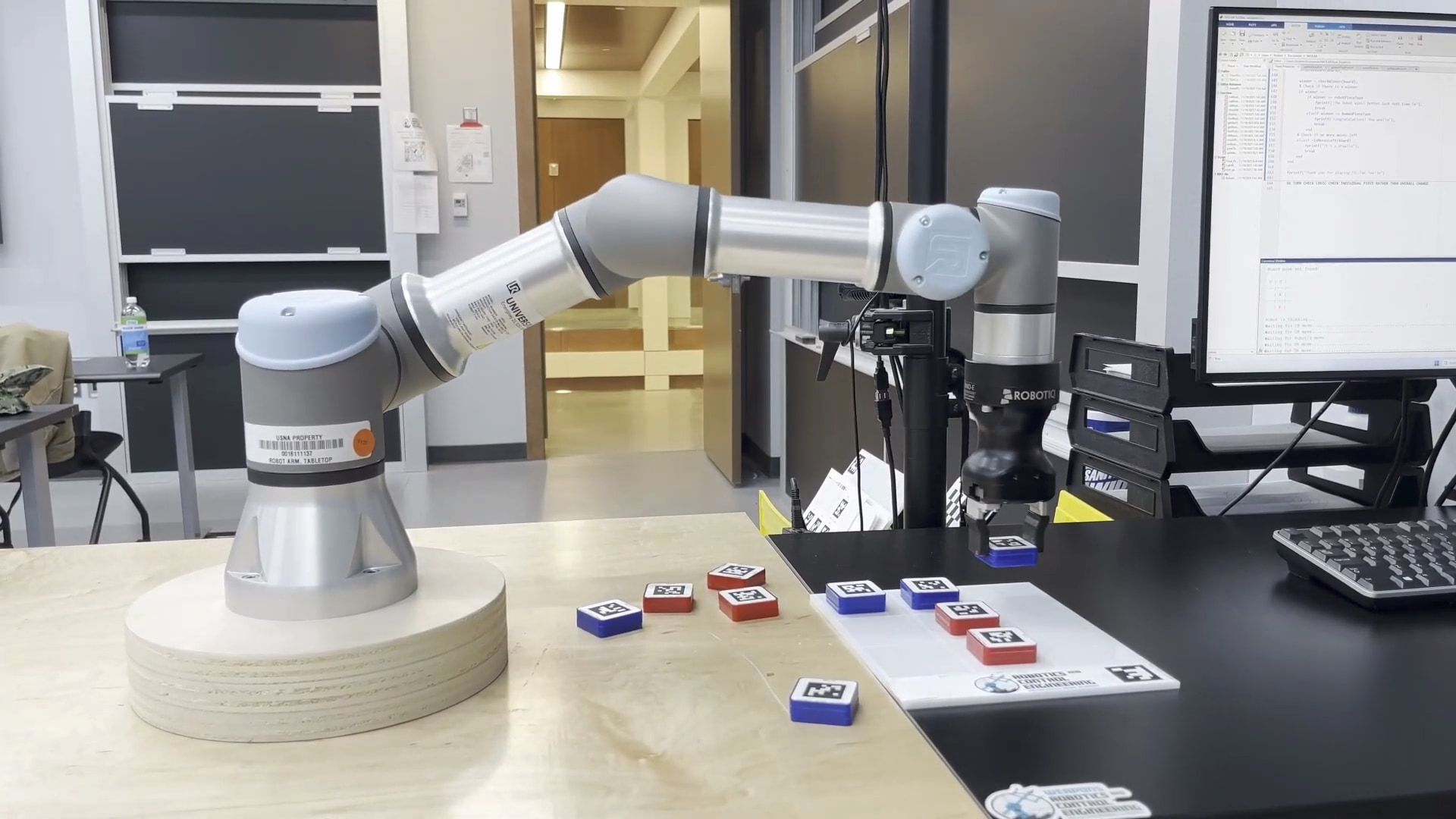
This system demonstrates the application of articulated robot modeling, forward and inverse kinematics, workcell layout, and computer vision. The UR3e, a six-axis robotic arm, serves as the physical agent, tasked with perceiving the game state, computing the optimal move, and physically executing that move by manipulating game pieces on a board.
To achieve this, the software architecture combines three distinct subsystems:
- Computer Vision: To detect the board state and human moves.
- Game Logic: Utilizing the Minimax algorithm to ensure the robot plays optimally.
- Motion Control: Utilizing Inverse Kinematics to translate board coordinates into precise joint movements.
This report details the design and implementation of these subsystems, analyzing the mathematical foundations and software logic that allow the UR3e to function as an intelligent, autonomous adversary.
Computer Vision
Located above the robotic arm is a calibrated monocular camera used to recognize the game board and game pieces. The system relies on AprilTags (family: tag36h11) for robust fiducial marker detection.
Board and Piece Detection
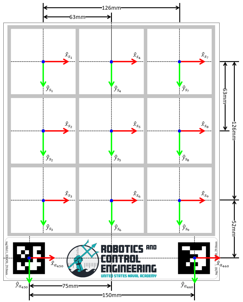
The board is recognized via two AprilTags (ID: 450 and 460, Size: 29mm). The program detects the board pose if it can see either tag; if both are visible, it averages the board's center pose. The specific position of each grid cell relative to these tags is described in figure below.
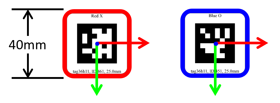
The system identifies game pieces using unique AprilTags (Size: 25.0mm).
- Red "X" Pieces: IDs 461–465
- Blue "O" Pieces: IDs 451–455
The program updates the board and piece poses at a rate of 2Hz. To update the game state, the system calculates the Euclidean distance between the center of a detected piece and the center of a grid cell; the cell is considered filled if this distance is minimized for a specific piece.
Game Logic
To ensure the robot competes effectively, the decision-making engine is built upon the Minimax algorithm. This is a recursive backtracking algorithm widely used in decision theory and game theory for zero-sum games—games where one player's gain is equivalent to the other's loss.
In this context, the robot acts as the Maximizer, seeking to maximize its score, while the human opponent is modeled as the Minimizer, seeking to minimize the robot's score.
Algorithm Execution
The algorithm simulates the game by constructing a Game Tree, exploring all possible future moves from the current state down to the terminal states.
- State Evaluation: Terminal states are assigned numerical values:
- +10: Robot wins.
- -10: Human wins.
- 0: Draw.
- Backtracking: Values are propagated up the tree. At each layer, the Maximizer chooses the move leading to the highest value, while the Minimizer (simulating optimal human play) chooses the move leading to the lowest value.
- Optimality: By assuming the human will always play the best possible move, the robot ensures it selects a strategy that minimizes the maximum possible loss. This guarantees the robot will never lose if it plays first and will force a draw or win if the human makes a mistake.
Motion Control
While the Minimax algorithm determines the target location in Cartesian space (), the UR3e requires joint angles () to reach that position. This mapping is achieved through Inverse Kinematics (IK), which calculates the specific angle for each of the robot's six joints required to reach a desired pose.
For reference, Figure 1 displays the UR3e manipulator's 6 joint poses.
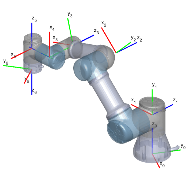
Figure 1: UR3e manipulator joint poses
Assumptions and Constraints
Solving the IK problem is non-trivial due to non-linear mapping and multiple possible solutions (e.g., "elbow up" vs. "elbow down"). The derivation is performed under the following assumptions:
- Downward Facing End-Effector: The z-axis of the end-effector opposes the base z-axis:
- Wrist Constraint: This orientation requires the fifth joint to be fixed at .
- Task Variables: The target is defined by position and gripper orientation .
Geometric Derivation
The joint angles are derived using a geometric decomposition of the manipulator.
Step 1: Base Rotation ()
Figure 2 displays the Top-Down view of the robotic arm used to derive the base angle.
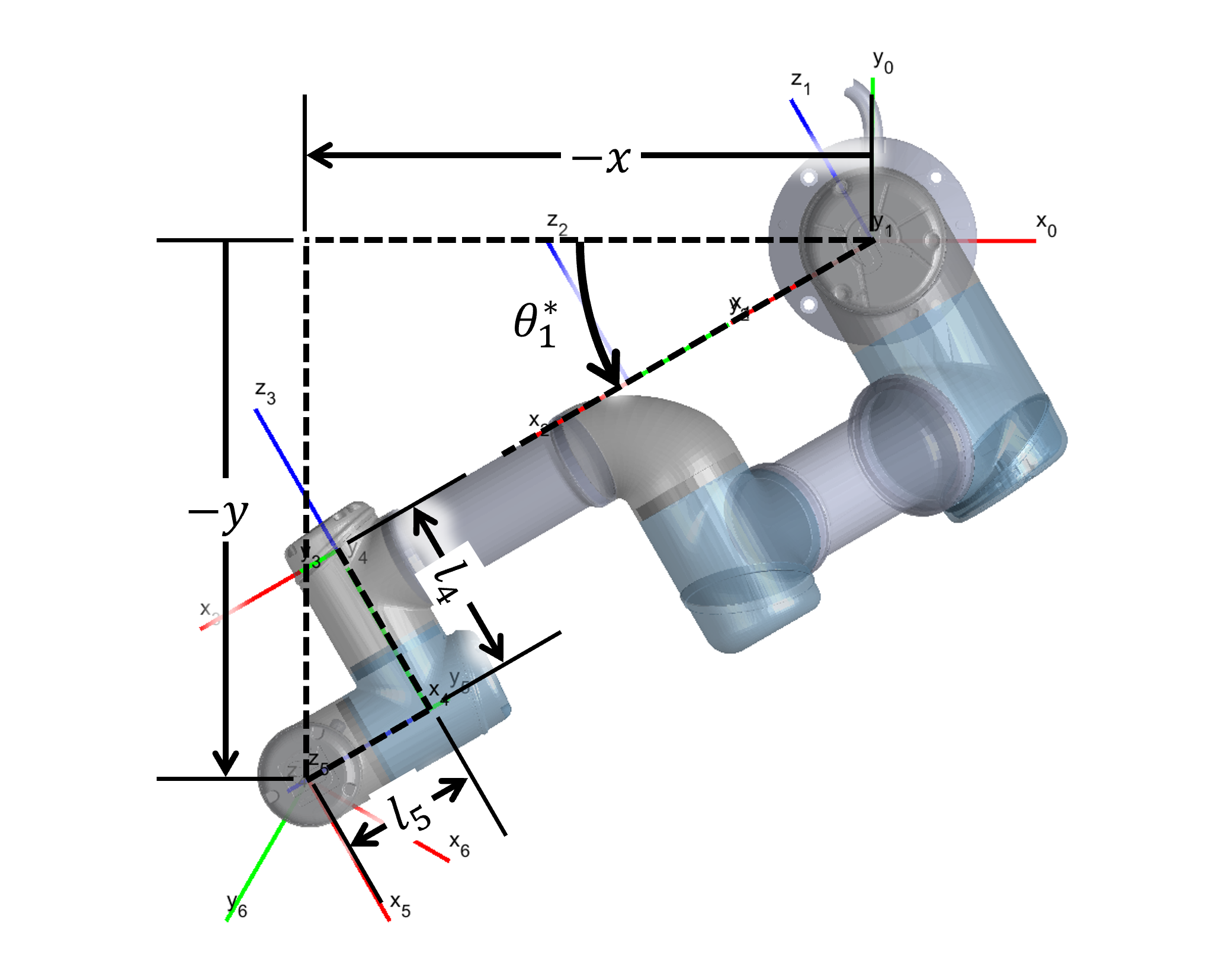
Figure 2: Top-Down view of the robotic arm
Based on the geometry shown in Figure 3, we define intermediate variables to solve for the base rotation.
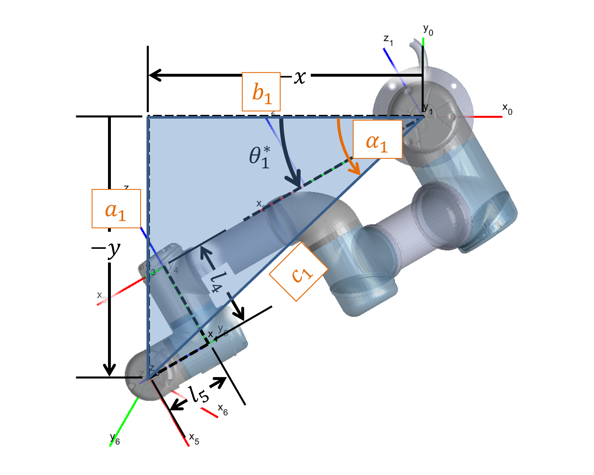
Figure 3: Derivation of equations 1-4
Figure 4 displays how equations (5)–(7) are derived to account for the offset .
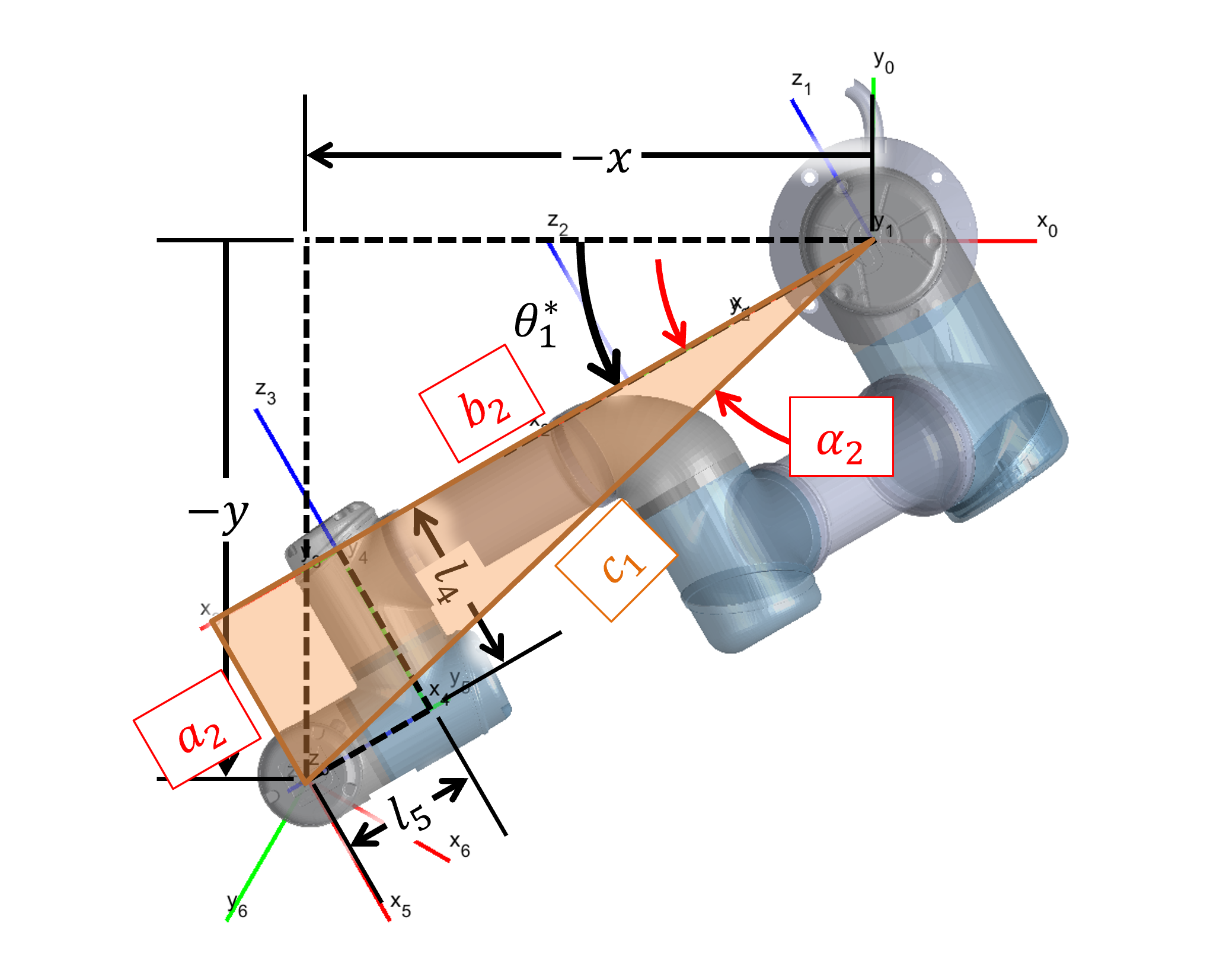
Figure 4: Derivation of equations 5-7
The angle for the base joint is then calculated as:
Step 2: Shoulder and Elbow () To determine the link lengths in the planar view, we refer to Figure 5.
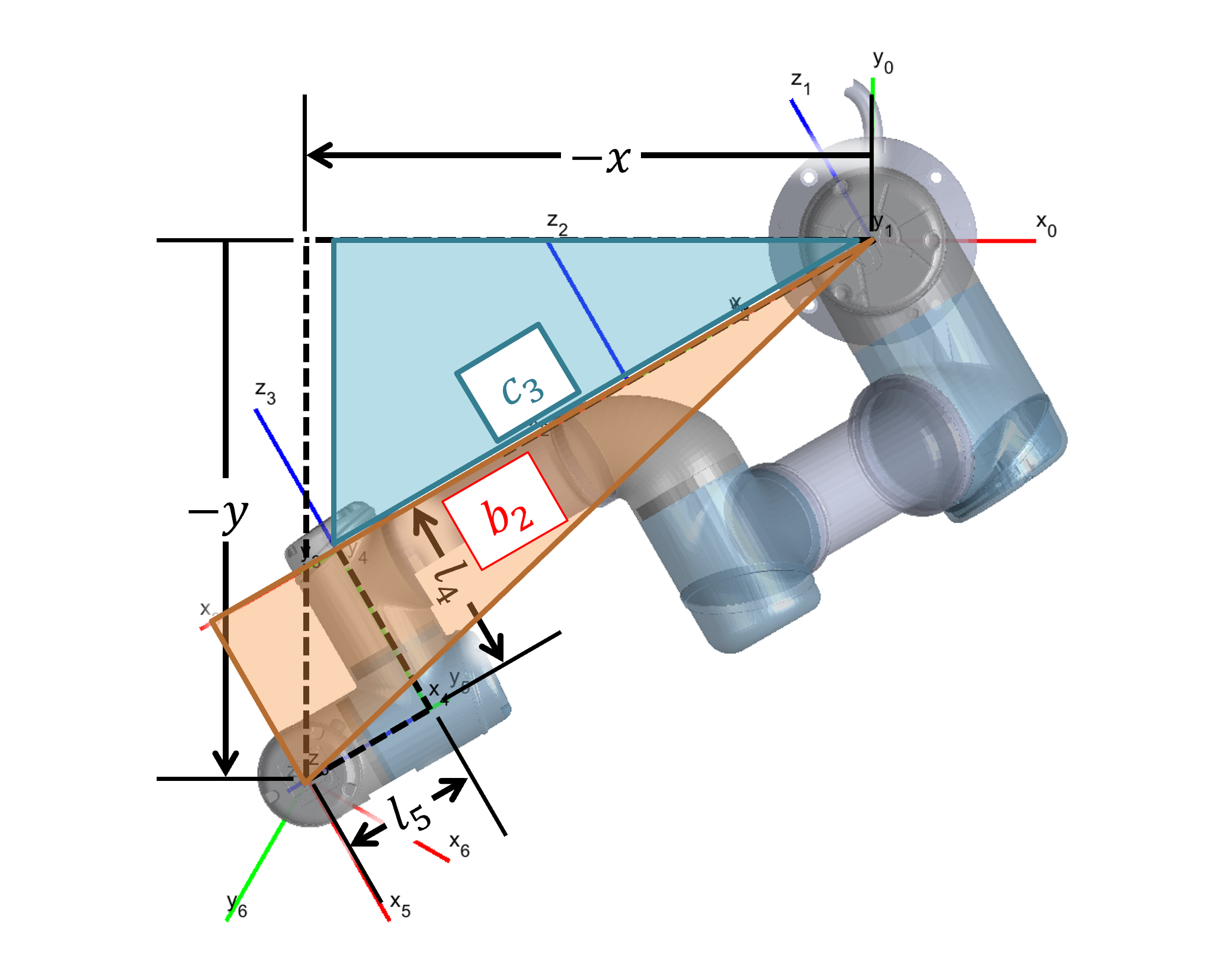
Figure 5: Derivation of equation 9
Figure 6 displays the Plane of the Manipulator view used for the subsequent calculations.
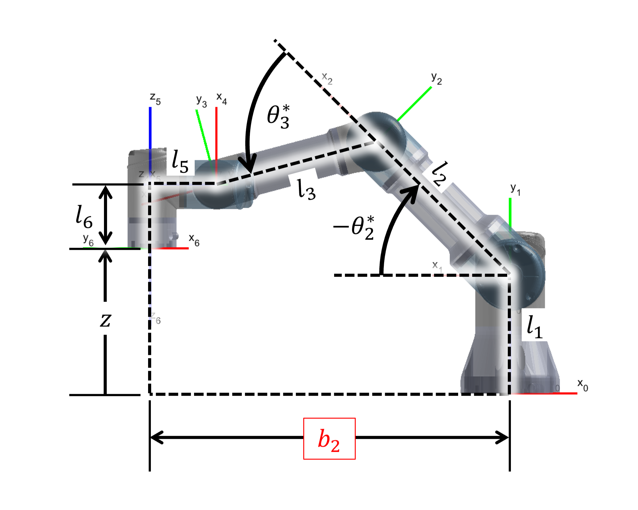
Figure 6: Plane of the Manipulator view
As shown in Figure 7, we define the vertical and hypotenuse components for the target reach.
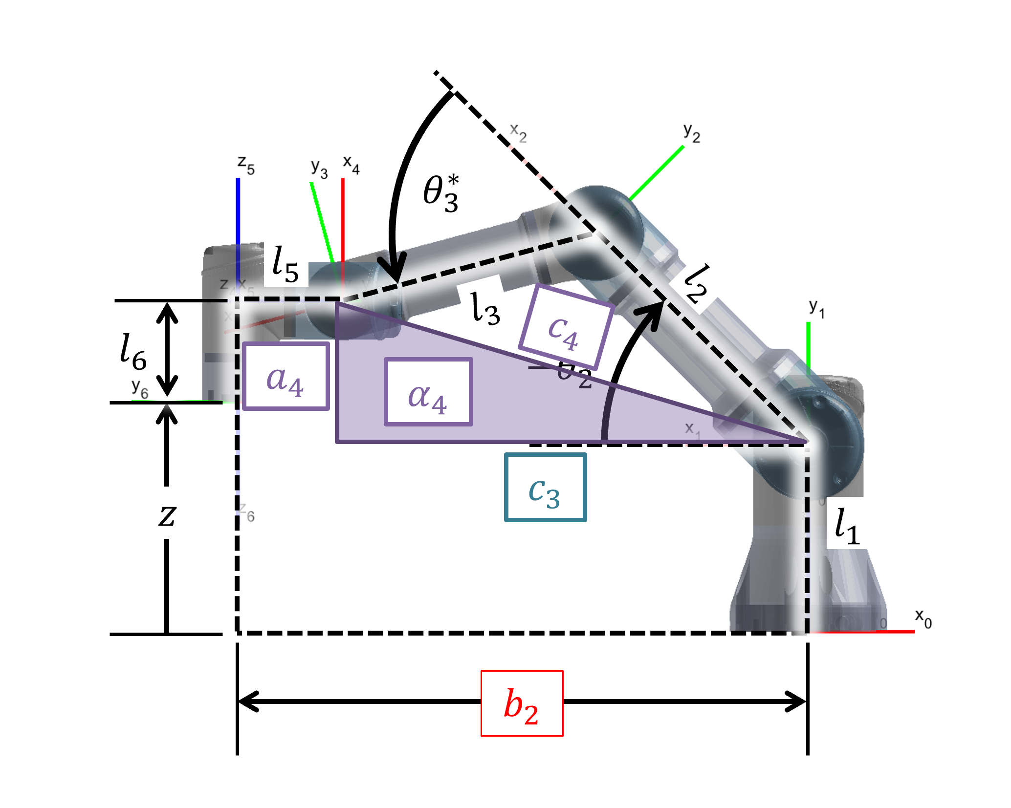
Figure 7: Derivation of equations 10-12
Using the Law of Cosines as derived in Figure 8, we solve for the internal angles of the arm triangle.
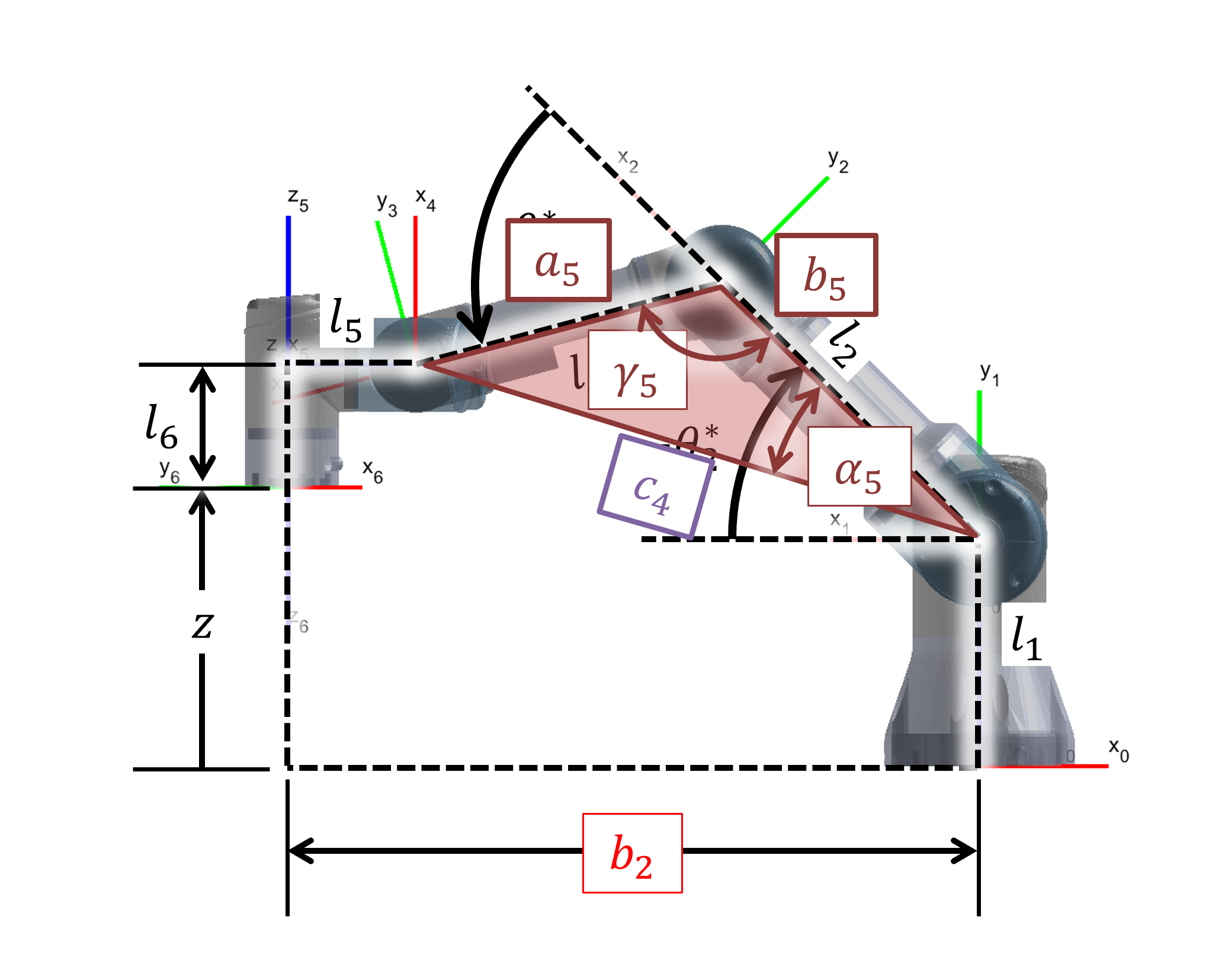
Figure 8: Derivation of equations 13-16
Figure 9 displays how Joint angles 2 and 3 are derived from these components.

Figure 9: Derivation of Joint angles 2 and 3
The system uses the Elbow-Up solution:
Note: An Elbow-Down solution is also mathematically possible but was not required for the robot.
Step 3: Wrist Orientation () Figure 10 displays how joint angle 4 is derived to maintain the downward orientation.
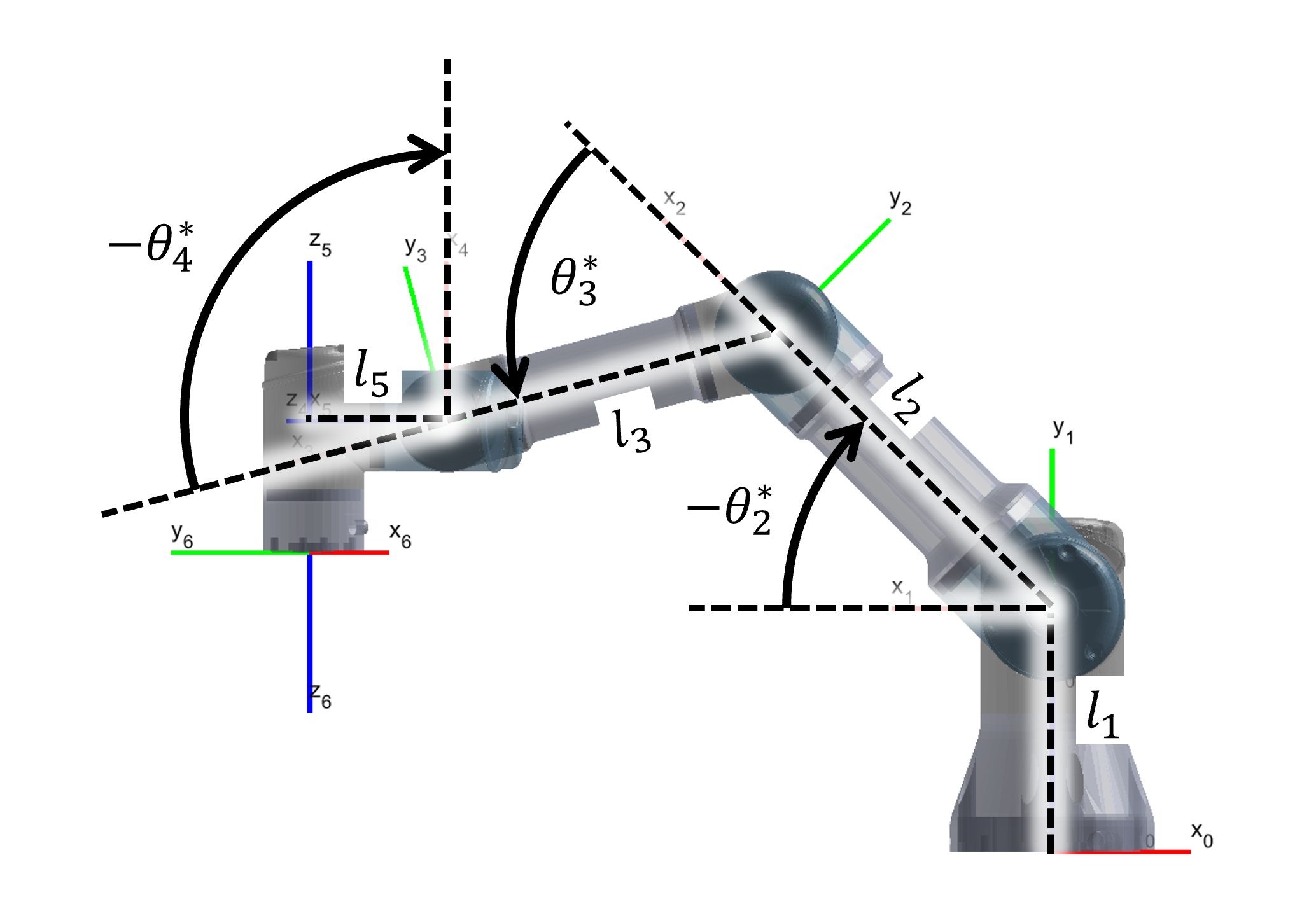
Figure 10: Derivation of joint angle 4
Finally, Figure 11 displays how joint angle 6 is derived to control the gripper rotation.
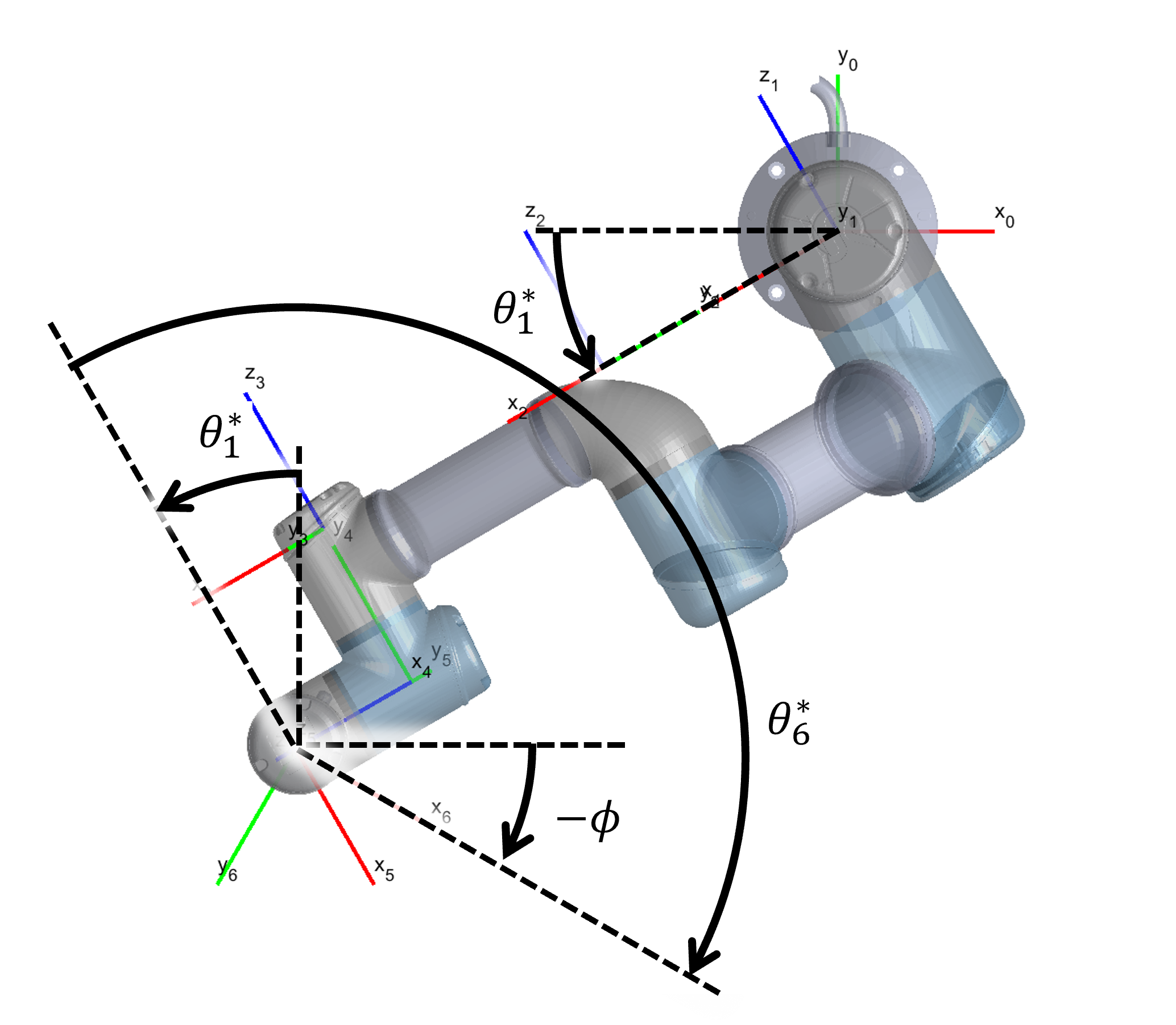
Figure 11: Derivation of joint angle 6
With equations (8), (17), (18), (19), and (20), the system can calculate the required joint angles to reach any reachable pose.
System Integration
With a method to extract piece poses, strategize moves, and control the robot to a desired position, we can put it all together into a fully autonomous system. The program starts by asking the player what piece type they want to play with and who wants to start first.
The robot plays against the player in a continuous loop:
- Update Board Status: Extract the board pose and piece poses.
- Determine Move: If it is the robot's turn, it uses the Minimax algorithm to determine the best move.
- Execute Pick-and-Place:
- The system finds a piece of the correct type that is not on the board.
- It uses the detected piece pose and Inverse Kinematics to calculating the joint angles required to pick up the piece.
- It then uses Inverse Kinematics to place the grabbed piece onto the grid cell aligned with the best move.
This process repeats until the game is determined to be a draw or a winner is determined.
Conclusion
This project successfully demonstrated the capability of the UR3e robotic arm to function as an autonomous agent in a structured game environment. By effectively synthesizing computer vision for state estimation, the Minimax algorithm for strategic decision-making, and geometric inverse kinematics for precise motion control, the system achieved robust gameplay against human opponents.
The implementation of the Minimax algorithm ensured that the robot never lost a match when playing first, validating the effectiveness of the game logic. Furthermore, the geometric IK solver proved computationally efficient and accurate, allowing for smooth pick-and-place operations within the robot's workspace. Overall, the system serves as a comprehensive proof-of-concept for human-robot interaction and autonomous manipulation tasks.