DC Motor Position Control
August 2024 - December 2024
Introduction
My third major course at USNA was EW305H (Honors Linear Control Engineering). We learned the fundamentals of classical control engineering, to include mathematical modeling, time and frequency response analysis, and design of PID compensators.
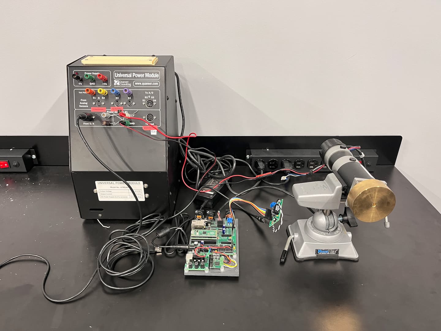
The final project of the course was to design a DC motor position controller under high magnitudes of static friction.
Design Documentation
The following documentation provides a brief overview of the design process to create a controller within the project's specifications. It involved both a simulation under frictionless conditions as well as experimental trials under a high friction load.
System Identification
The first step in designing a controller is to identify the system. I used a step input of magnitude 3 volts to the motor and recorded the response. The data was then used to identify the transfer function of the system.
The DC motor transfer function from voltage to speed can be modeled as follows:
Where constants and can be estimated through time response analysis of the motor at the given step input voltage. My trials calculated and .
The DC motor transfer function from voltage to position can be modeled as follows:
As a result, we can model the DC motor's position transfer function as follows:
The design specifications was a overshoot with a settling time, , dependant on the chosen controller design and the constant .
Lead compensator
As the DC motor transfer function is Type-1, we can expect a zero steady state error. Therefore, a lead compensator would be a very simple approach to achieve the design specifications. The lead compensator transfer function is the following:
Where the zero, , and pole, , can be calculated via the Root Locus Method. A of 9.0915 and of 25.3115 with a gain value was calculated for the following controller function:
The Root Locus for the lead compensator is illustrated in Figure 1.
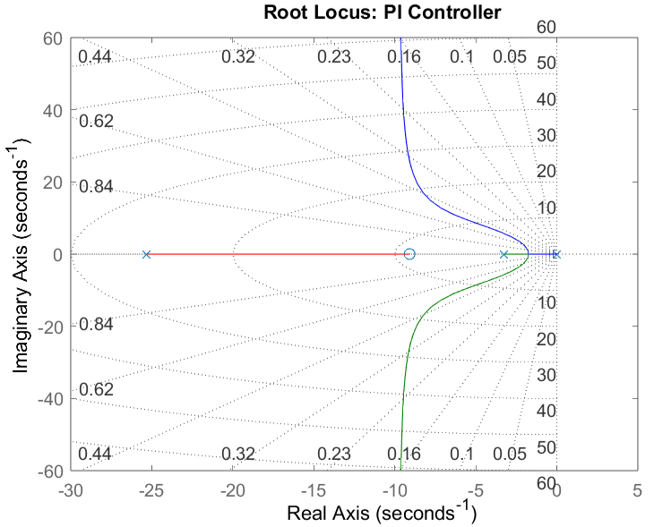
Figure 1
In order to discretize the lead compensator transfer function, Tustin approximation was implemented to transform the function into the z-domain:
Where is the sampling time of 0.01 seconds as the motor encoder samples at 100 Hz. Utlizing the time shift theorem to transform back into the time domain yields:
Where is the error signal. Implementing the lead compensator to the DC motor yields the following results:
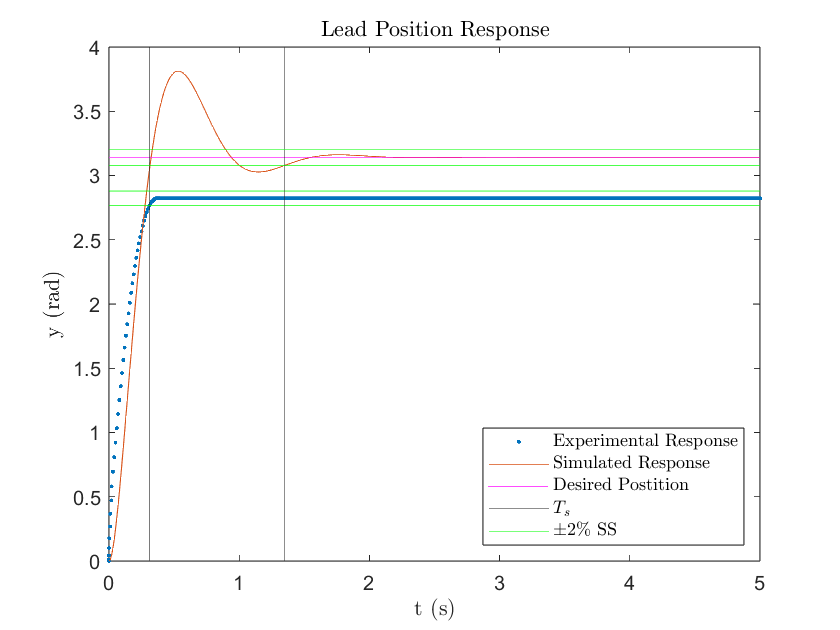
Figure 2
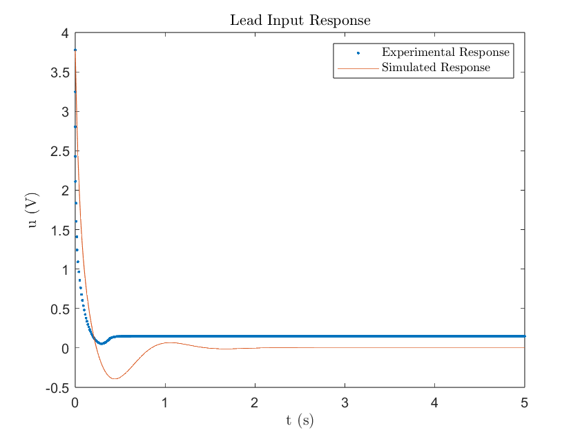
Figure 3
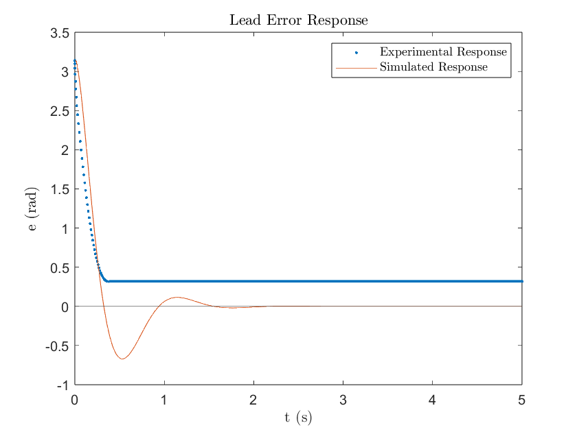
Figure 4
The simulated lead compensator met the settling time requirement of 1.3647 seconds with a 1.35 second settling time. However, it went over the required percent overshoot of less than 16% with a 21% overshoot. This can be associated with the zero being a little too close to the origin as seen in Figure 1. The simulated response also achieved a zero percent steady state error (SSE) which is expected for a Type-1 plant. Additionally, the initial value of the control input matched within range what's expected, . Where and , for a . Both the simulated and experimental response had an initial input voltage of 3.78 volts which is slightly lower than theoretical. This can likely be attributed to the discretization of the lead compensator.
The experimental lead compensator displayed a much different response compared to what was simulated. Technically, it achieved a fast settling time (0.31 seconds) and low percent overshoot (0%), but it failed to reach the desired position. The steady state error was -0.3191 rad which means the lead compensator stabilized under the desired position as seen in Figure 2. The simulated response demonstrated how a Type-1 plant will result in zero SSE so the existence of SSE in the experimental response clearly outlines the existence of an external disturbance. In the case of the DC motor, the constant disturbance was friction. As the lead compensator’s error decreases with time, its input voltage decreases because it's proportional to the error measured. The derivative part of the lead compensator aims at driving the change in error to zero, which results in a quicker settling time, but it fails to help the small control input to overcome the friction force. As a result, the motor gets stuck under the desired position and does not have enough voltage to move further. This can be visually observed in both Figures 3 & 4. Notice how the input voltage gets very small when the error decreases and steadies out at a value very close to zero volts.
PI Controller
Due to the lead compensator’s failure to achieve zero steady state error, a PI controller was designed. The PI controller combats error in the response and whose transfer function is the following:
Where the zero can be calculated via the Root Locus Method. A of 0.72 with a gain value was calculated for the following controller function:
The Root Locus for the PI controller is illustrated in Figure 5.
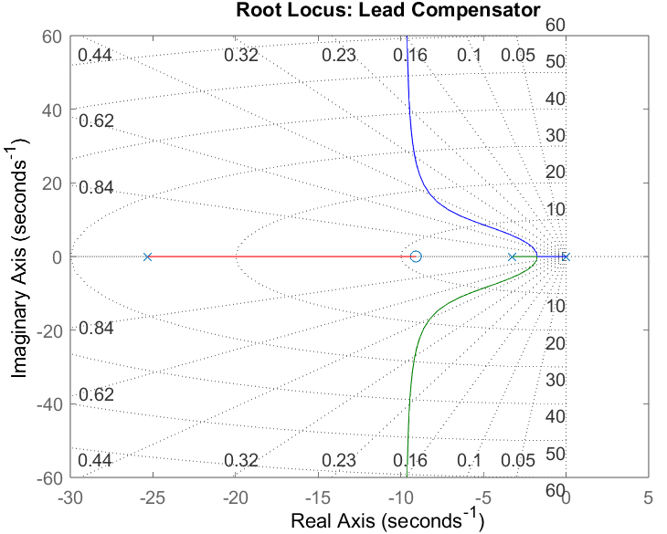
Figure 5
In order to discretize the PI compensator transfer function, Tustin approximation was implemented to transform the function into the z-domain:
Where is the sampling time of 0.01 seconds. Utlizing the time shift theorem to transform back into the time domain yields:
Implementing the PI controller to the DC motor yields the following results:
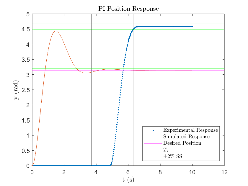
Figure 6
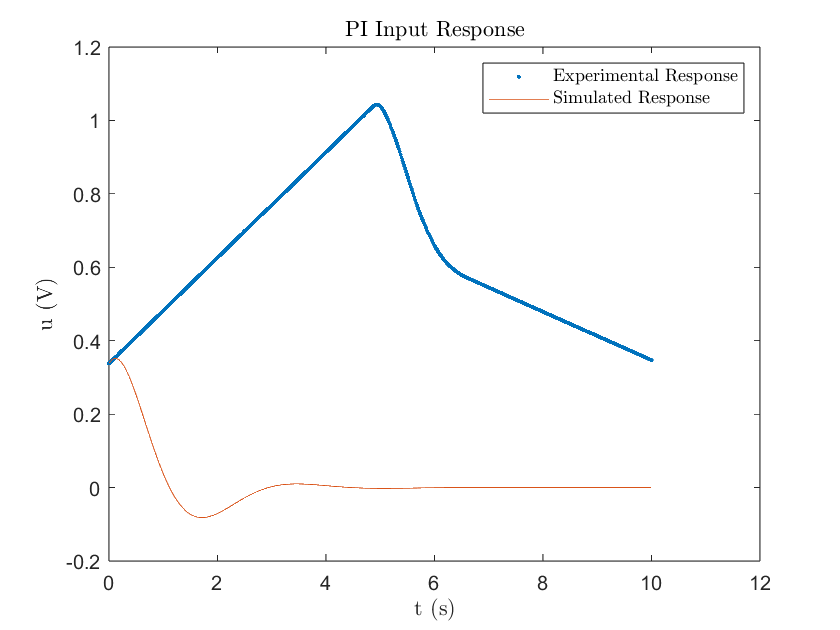
Figure 7
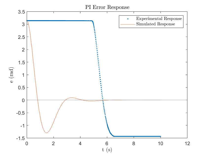
Figure 8
The required settling time for the PI controller was 3.6847 seconds, which matched the simulated settling time of 3.7 seconds. The simulation, however, failed to meet the percent overshoot requirement of less than 16% and ended up with a 41% overshoot. This highlights the limitation of PI control and is a result of the zero being very close to the origin as observed in Figure 5. The simulation did however reach zero steady state error which is expected for PI control.
Unfortunately, the experimental response told a different story with a settling time of 6.304 seconds. This was a result of the “wind up” effect produced by PI controllers when there is a high degree of stiction, which is why the experimental motor did not have enough initial voltage to overcome the static friction force and remained at rest. With time, the integral of the error would gradually build up as seen in Figure 7. As soon as the motor reached a high enough voltage to overcome the stiction, the controller quickly decreased the input as a result of the decrease in error. It was unable to decrease the motor voltage quick enough, resulting in an overshoot. By this time, the motor angle position is greater than desired, so the controller aims at reversing its direction to correct for the error. However, the input voltage is still positive and is gradually decreasing as the integral of the error gets increasingly more negative as seen by both Figure 7 & 8. As a result, the motor got stuck above the desired position with an experimental steady state error of 1.4358 rad. If we let this program continue to run, we would potentially observe that the input voltage would finally decrease enough to overcome stiction and attempt to decrease the error response.
PI Lead Compensator
Due to the PI controller’s failure to achieve the specified settling time, both the Lead compensator and PI controller were designed in tandem to create a PI Lead compensator. The PI Lead compensator transfer function is the following:
Where the zeros and with pole can be calculated via the Root Locus Method. A of 4.454, a of 3.375, and a of 27.22 was calculated with a gain value of for the following controller function:
The Root Locus for the PI Lead compensator is illustrated in Figure 9.
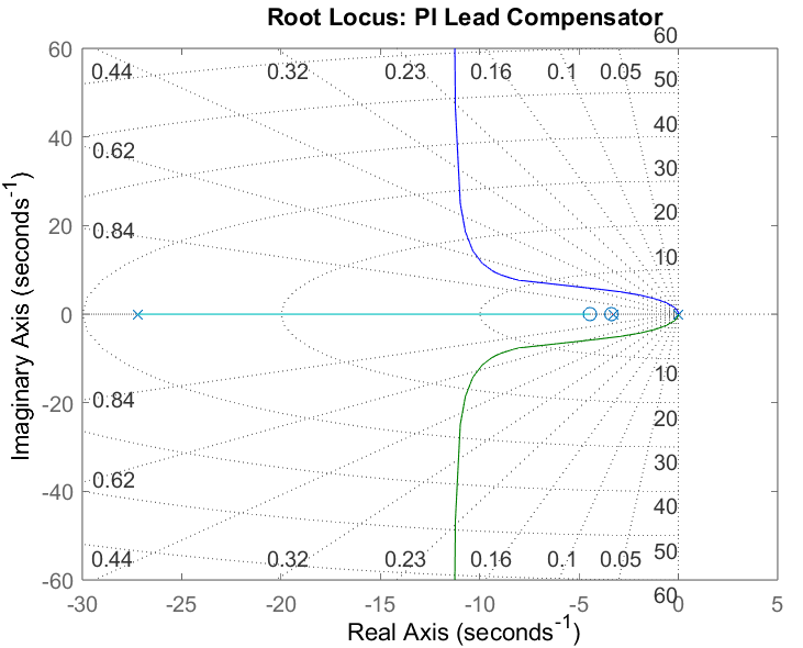
Figure 9
In order to discretize the PI Lead compensator transfer function, we can utilize the previous Tustin approximations to transform the function into the z-domain:
Where is the sampling time of 0.01 seconds. Utlizing the time shift theorem to transform back into the time domain yields:
Where is the intermediary voltage between the PI controller and lead compensator. Implementing the PI Lead compensator to the DC motor yields the following results:
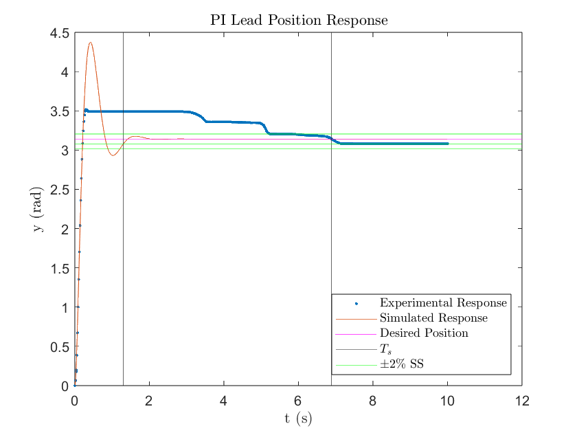
Figure 10
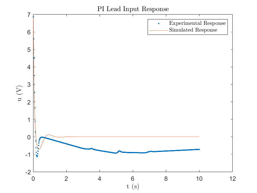
Figure 11
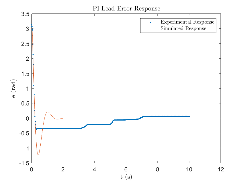
Figure 12
The simulated response matched the required settling time of 1.31 seconds with a 1.30 second settling time. Unfortunately, it still exceeded the required 16% overshoot with a 39.3% overshoot. This can be attributed to the PI controller’s influence on the system with the zero being close to the origin as seen in Figure 9. With a Type-1 plant, a zero SSE was expected and achieved in the simulation response. Additionally, the initial value of the control input matched within range what's expected, . Where and , for a . Both the simulated and experimental responses had an initial input voltage of 6.85 which is slightly lower than theoretical. This can likely be attributed to the discretization of the PI Lead compensator.
Following the trends of the previous controller designs, the experimental response was significantly different compared to what was simulated due to stiction. As a result, the settling time lagged what was simulated with 6.88 seconds but the percent overshoot requirement was accomplished with only a 14.1% overshoot. Additionally, a small SSE of 0.14 rad was observed. The much higher gain value due to the lead compensator significantly reduced the “wind up” effect characterized by the PI controller. You can see this in Figures 10 & 11 where the motor was able to overcome stiction almost instantly. Upon overshoot however, the motor got stuck again due to stiction. Fortunately, as seen in Figure 11, the motor voltage was able to decrease fast enough to become negative and reverse direction towards the desired position. Throughout this process however, it got stuck multiple times due to the fine adjustments in the motor voltage being very close to zero volts. As observed in the input response, the lead compensator tries to achieve steady state by slightly increasing the motor voltage. However, due to the voltage being nearly zero and the presence of stiction, the motor becomes stuck. As seen with the PI controller, the integral term is forced to decrease the voltage to get it moving again. Unfortunately, the controller undershot the desired position, but the rising “wind up” input response suggests that the motor will overcome stiction again to correct for the error.
Conclusion
This project helps to highlight the impact of external disturbances on control systems. The in case of the DC motor, a significant amount of stiction was experienced. In the simulations, the controllers were able to achieve short settling times and reasonable overshoots as they are modeled without any disturbances. The experimental trials, however, observed an environment with a high degree of stiction. As a result, the controller often times failed to overcome these friction forces and produced a significantly different response compared to the simulations.