Search and Rescue Rover
April 2026
Introduction
My tenth major course at USNA was EW458 (Programming & Planning For Mobile Robots). The course explores the use of modern programming tools to develop high-level mobile robot applications, covering core concepts such as mapping, autonomous navigation, algorithm design, and state machine logic.
The final project was to program a Create3 ground vehicle to autonomously navigate a search and rescue course, locate a target object, and return to the starting point. The robot had to use its 360-degree LiDAR sensor and camera to map the environment, plan a path to the target, and execute that path while avoiding collisions.
Demo Video
Design Documentation
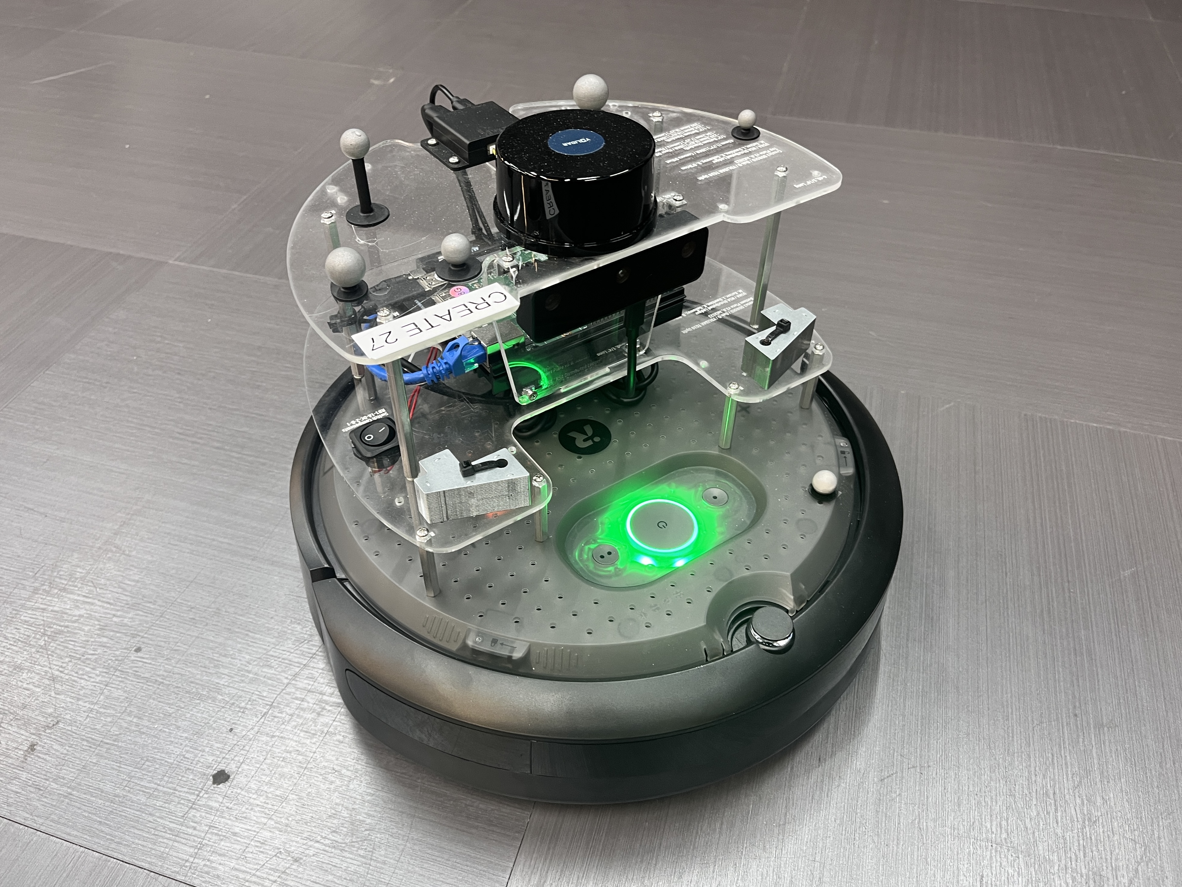
The search and rescue system utilizes an iRobot Create3 ground rover integrated with ROS2 to autonomously explore unknown environments, identify specific targets (green & orange cones), and navigate safely. The system is designed around a continuous loop of mapping the environment, identifying new areas to explore (frontiers), planning efficient paths, executing precise movements, and actively scanning for rescue targets.
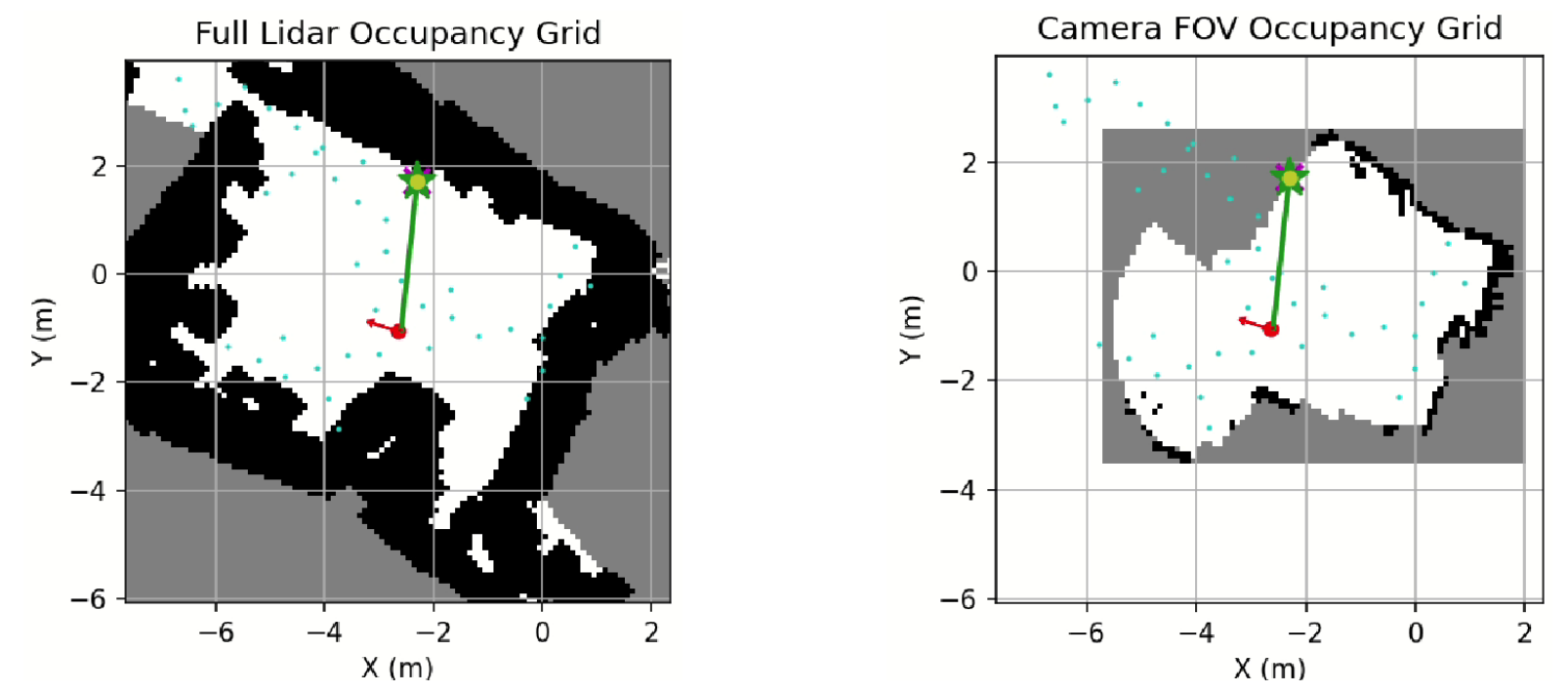
Mapping
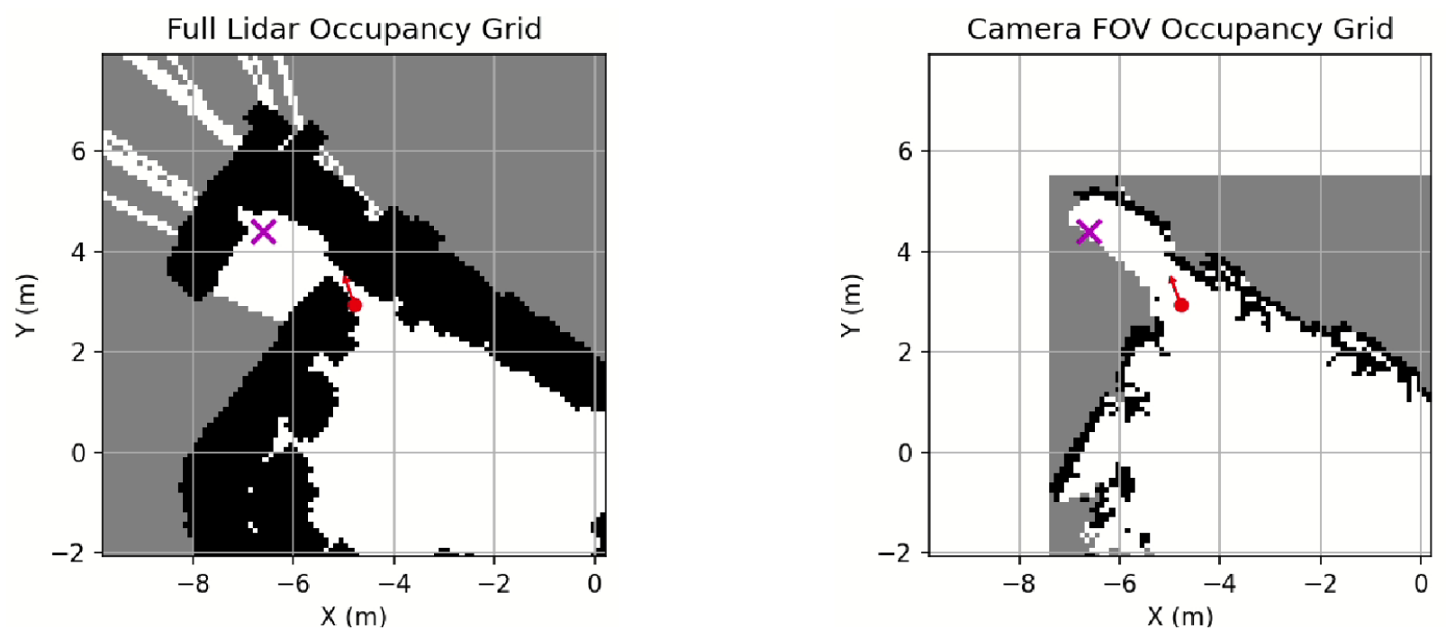
The foundation of the robot's autonomy is its ability to understand its surroundings in real-time. The standard map for robotic navigation is called an Occupancy Grid. It divides a space into squares of a known size to create a grid, where each cell is assigned a numerical value to represent a feature of the environment.
The system uses odometry to estimate the robot's position, while the LiDAR measurements provide the location of obstacles relative to the robot's body-fixed reference frame. In standard ROS mapping, -1 represents unknown space, 0 represents free space, and 100 represents a high probability of an obstacle.
Coordinate Transformations
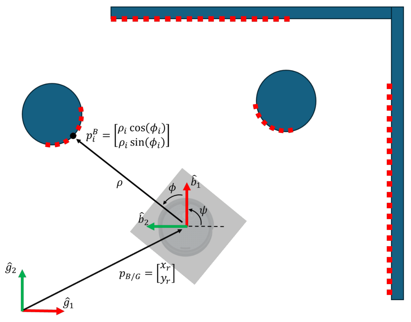
To build the map, the robot must convert raw Lidar scans into global map coordinates. The Lidar returns distance () and angle () to obstacles. First, a point is calculated in the robot's Body Frame using polar-to-Cartesian conversion:
Next, these points are mapped from the Body Frame to the Global Frame. Using the robot's global position and heading , the algorithm applies a rotation matrix and translation:
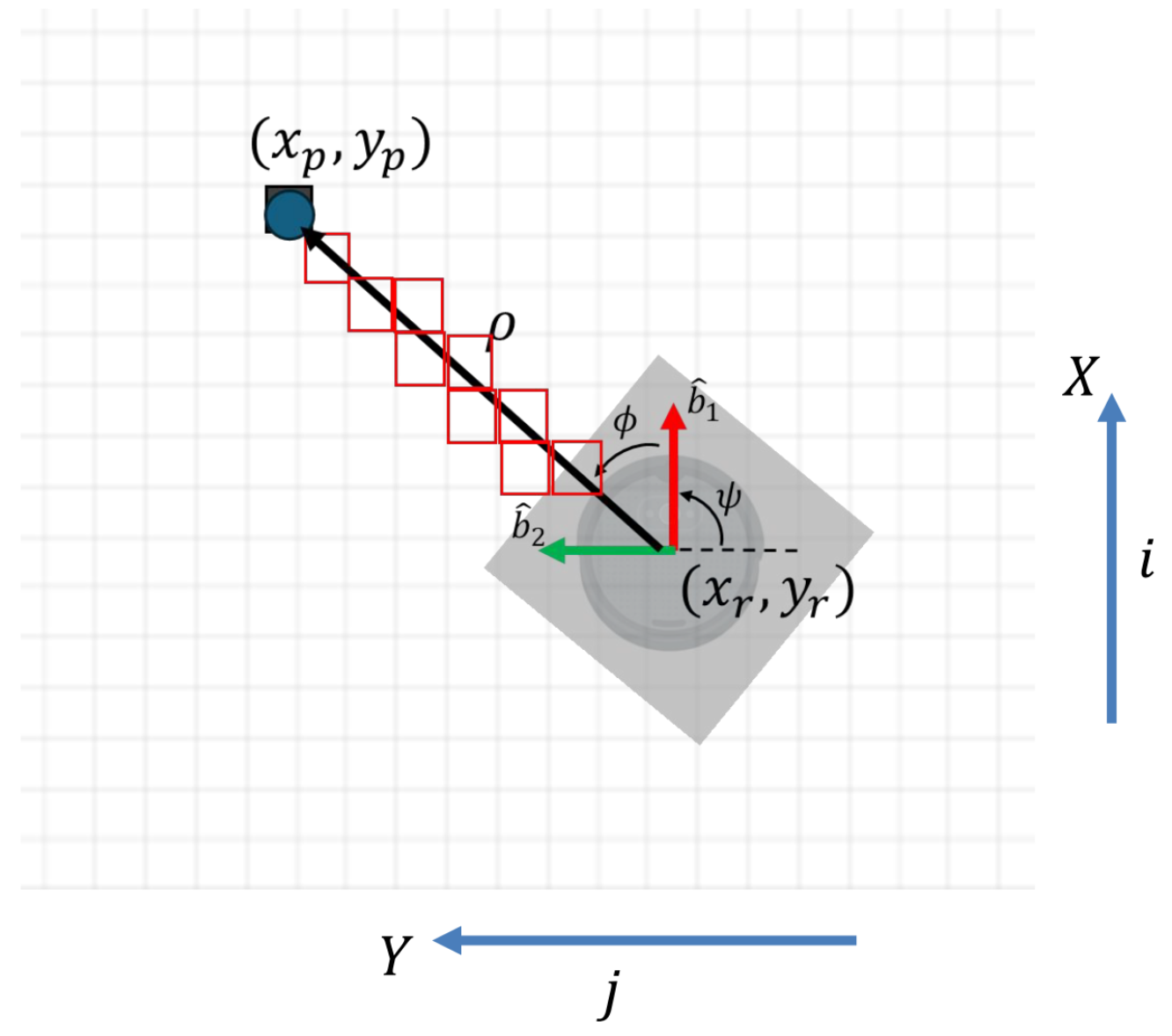
Spatial to Grid Conversion
To place this physical point into the digital matrix of the occupancy map, the spatial coordinates are converted to pixel indices. For a map with spatial resolutions and , the grid index is found by comparing the point against the map's minimum boundaries:
Ray Tracing (Clearing Free Space)
Every grid point on the ray connecting the vehicle position to the obstacle location must be free space. The algorithm clears all of the cells the laser passes through. For a ray with total distance , the system divides the ray into steps, where . At each fractional step , the intermediate coordinates are calculated:
These intermediate cells are marked as free, while the final endpoint is marked as an obstacle.
Frontier Selection
Once a map is generated, the robot must decide where to go next. It does this by finding "frontiers," which are the boundaries between known free space and unknown, unexplored space.
- FOV-Targeted Exploration: The robot specifically looks for frontiers within its camera's FOV map to ensure it is actively pointing its sensors at unexplored areas.
- Candidate Filtering: Not all frontiers are valid. The system filters out frontiers that are too close to walls (maintaining a 0.30m clearance) or do not have a minimum connected free area (0.5 square meters) to ensure the robot doesn't get stuck in tight corners.
- Goal Selection: Among the valid candidates, the algorithm prefers frontiers that are positioned near the edge of the camera's maximum range (3.0 meters) to effectively push the exploration outward.
Path Planning
With a frontier goal selected, the robot calculates a safe route using a Rapidly-exploring Random Tree (RRT) algorithm.
- Tree Generation: The algorithm samples random points in the map and iteratively builds a tree connecting these points toward the goal. It explicitly checks every path segment against the occupancy grid to ensure the route is entirely collision-free.
- Adaptive Planning: If the robot struggles to find a path, it dynamically scales down its expansion distance and increases its maximum iterations to navigate tighter spaces.
- Path Pruning (Shortcut Method): Raw RRT paths are often jagged and inefficient. To fix this, a pruning function applies a greedy shortcut algorithm. It iterates through the waypoints and attempts to connect the current position directly to the furthest possible waypoint in a straight line. If that direct segment is collision-free, it deletes all the redundant waypoints in between, resulting in a much smoother and faster route.
Waypoint Control
After a pruned path is generated, the robot relies on a custom proportional controller to navigate from waypoint to waypoint.
The Create3 robot utilizes a built-in inner loop controller to manage wheel speeds based on a desired forward velocity () and turn rate (). Therefore, the project focused on developing an outer-loop controller to calculate inputs and to drive the robot toward specific global coordinates.
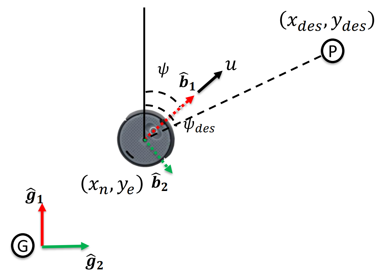
Control Logic
The controller uses Proportional Control to minimize the error between the current pose and the desired waypoint . The error terms are calculated as:
The desired heading () and distance to the target are derived from these errors:
The control inputs are then computed using proportional gains ( and ):
Tuning
The gains were tuned separately. Heading () was tuned first to achieve static heading accuracy, followed by the speed gain () to optimize travel time. Inputs were saturated to stay within the robot's physical limits.
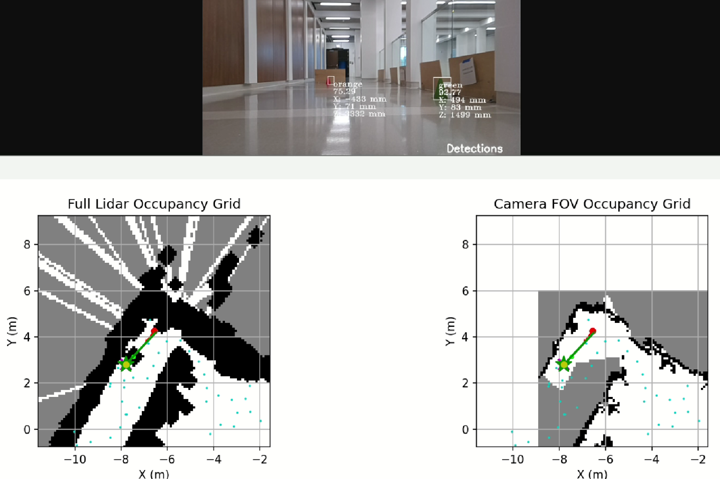
Target Detection and Mission Completion
The ultimate goal of the search and rescue mission is to locate specific targets in the environment—in this case, designated green and orange cones.
-
Vision Fusion: The system listens to a 2D object detection topic (running YOLO) and filters for specific class IDs representing the targets. Detections must meet a minimum confidence score of 0.60 and fall within the 66-degree camera FOV.
-
Target Tracking: To prevent false positives, a cone must be detected at least 5 times before it is officially logged. Once confirmed, the system maps the cone as a physical circular obstacle on the occupancy grid so the path planner avoids running it over.
-
Return to Base: Once both the green and orange targets are securely confirmed, the robot triggers a "return home" mode. It abandons frontier exploration, queries the RRT planner for a path back to its initial starting coordinates, and autonomously navigates home to conclude the mission.
System Performance and Results
The autonomous system was rigorously tested to evaluate its mapping accuracy, path-tracking capabilities, and target detection precision. The plotted telemetry data demonstrates highly reliable performance across the entire search and rescue mission.
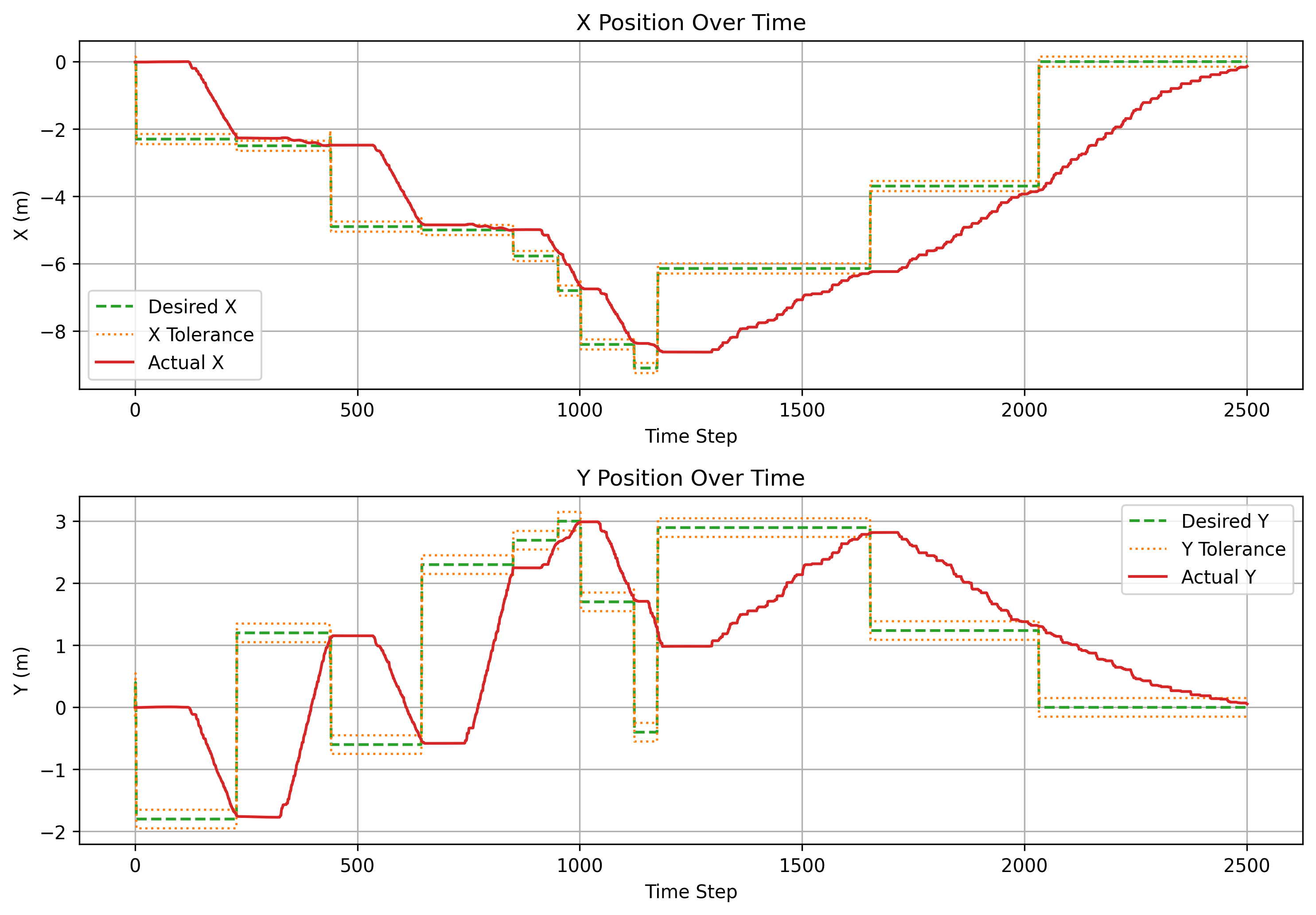
Path Tracking and Navigation
Telemetry tracking overlaying the desired path against the actual robot path shows that the system tightly adheres to the RRT-generated routes. The custom waypoint controller enforces strict operational bounds to ensure precision:
-
Position Tolerance: The robot accurately tracks the desired X and Y coordinates over time, reliably staying within a predefined waypoint threshold of +/- 0.15 m.
-
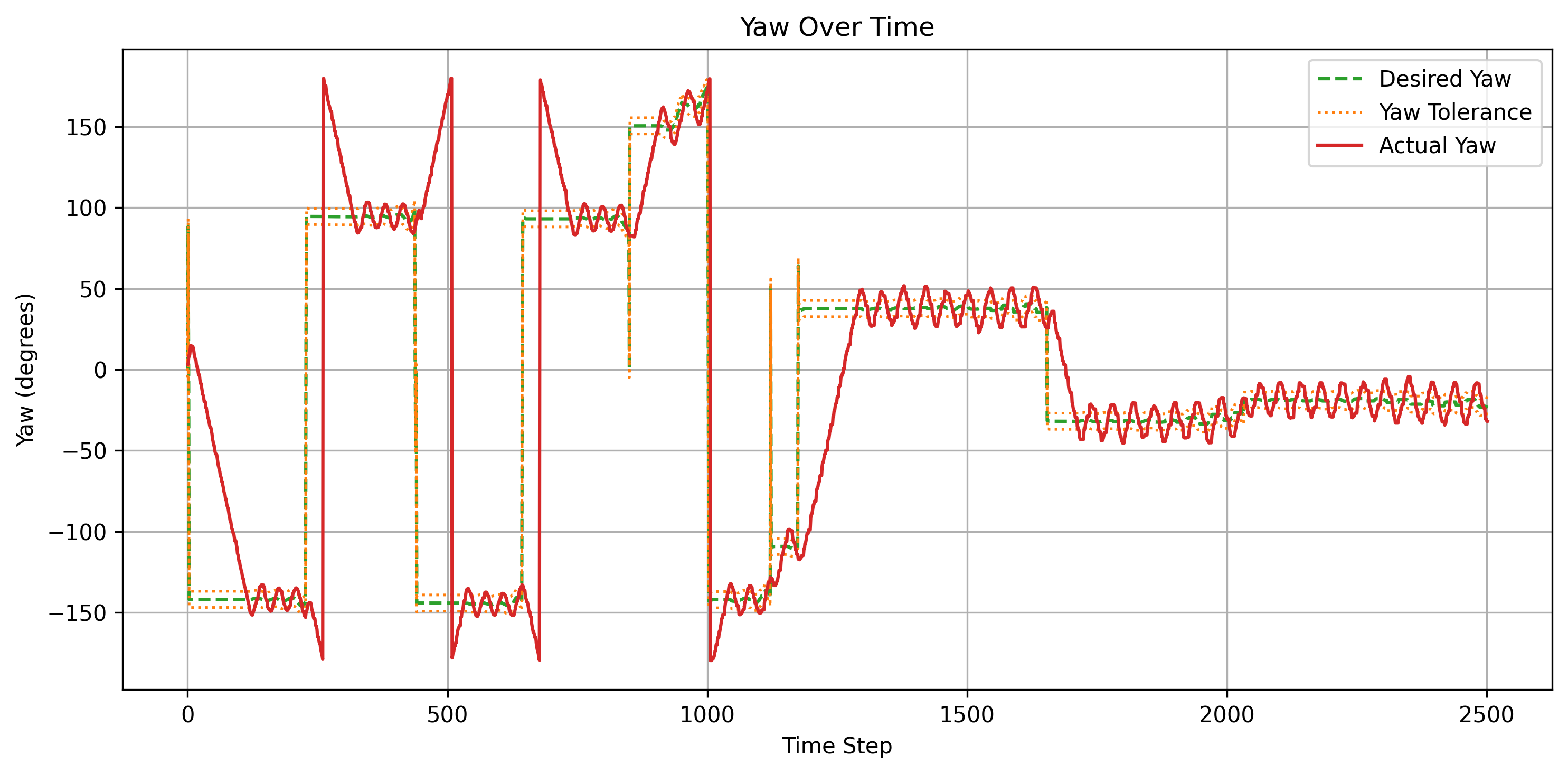
Heading Tolerance: The robot consistently maintains its desired heading within a strict yaw threshold of +/- 5 degrees.
-
Error Convergence: Position and yaw error graphs display predictable, stable behavior; errors naturally peak when transitioning to a new waypoint but smoothly converge to near zero as the proportional controller corrects the robot's trajectory.
Quantitative Error Metrics
Post-mission data analysis yielded the following average error rates, highlighting the overall effectiveness of the integrated sensors and control algorithms:
| Performance Metric | Average Error |
|---|---|
| Position Tracking | 0.08 m |
| Yaw / Heading | 0.08 deg |
| LiDAR Mapping | 0.11 m |
| Target Detection | 0.36 m |
| Return Home | 0.17 m |
Ultimately, the combination of a low-error LiDAR map (0.11 m) and a tightly tuned proportional controller allows the system to autonomously explore its environment, detect objectives, and successfully return to its origin point with an accuracy of 0.17 m.